clock dentistry and lantern pinion rebuild
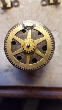
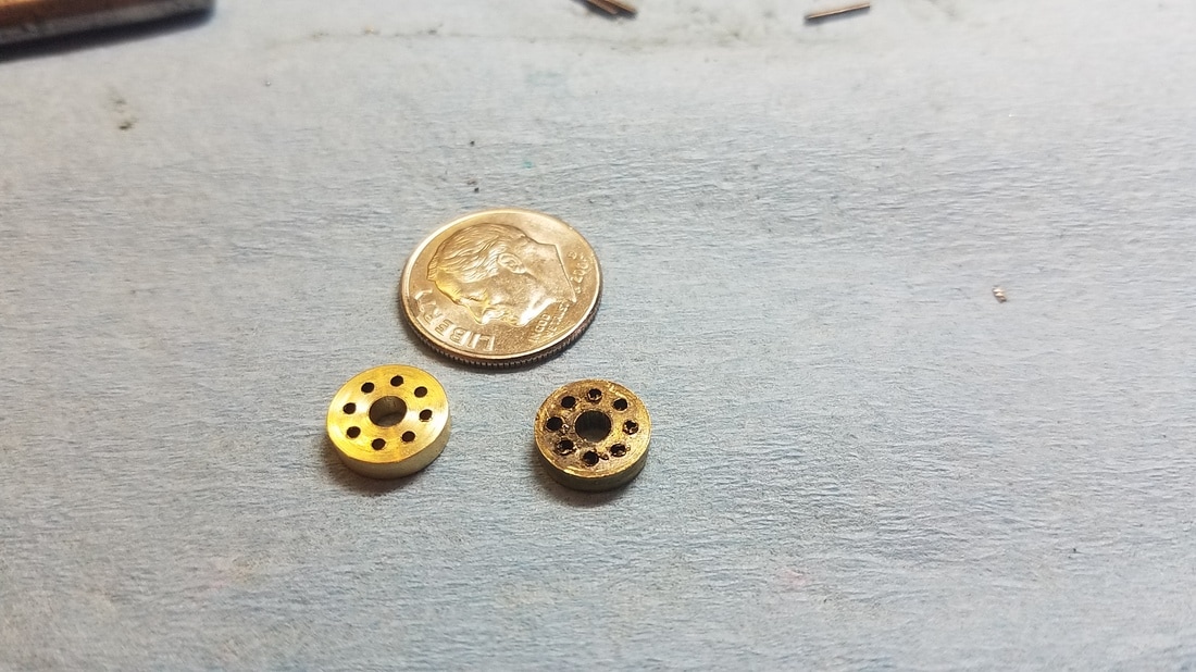
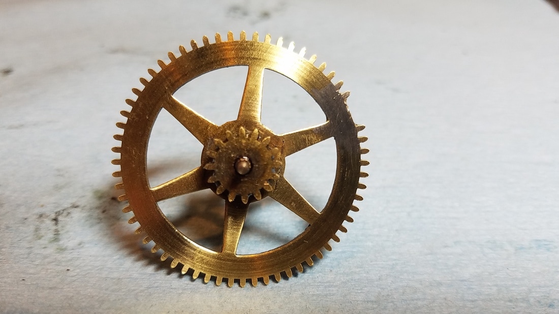
This wheel is the second wheel on the strike side out of a New Haven Kitchen clock. The clock was no longer striking. This was not the only problem with the clock but it was the one that took the most time to repair. Some repairman in the past had soldered a small piece from a similar wheel to this wheel where a few teeth had been bent or were missing. This actually worked quite well but I wanted to do a more conventional repair. The lantern pinion on this wheel had 3 bent trundles and upon closer inspection there were 3 different sizes of trundles installed. As I started to replace the trundles I found that the upper lantern pinion shroud had all the trundle holes drilled oversize causing all the trundles to be very loose with a lot a shake. The holes in the lower shroud seemed to be OK. I decided the best repair was to make a new upper shroud and replace all the trundles. I thought it might be interesting to some so I decided to document the procedure.
Feel free to contact me if you have a question about this procedure. My info can be found on the 'Contact' page.
Feel free to contact me if you have a question about this procedure. My info can be found on the 'Contact' page.
Click on any image for a full size photo.
|
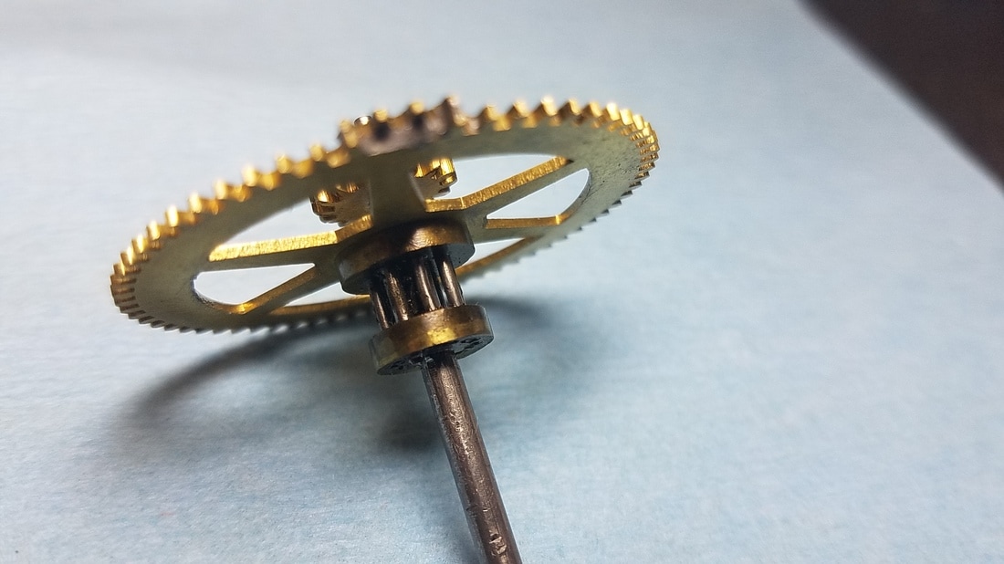
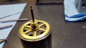
A view of the bad lantern pinion. It is difficult to see in the picture that some of the pins are slightly bent. The bigger problem was that there was too much side to side shake for all the pins due to the holes in the upper shroud being drilled oversize at some point.
|
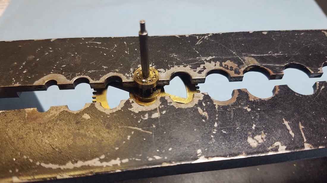
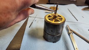
Putting the wheel assembly into a split stake so I can remove the upper shroud. You can see in this picture that one of the trundles was too long and sticking through the shroud.
|
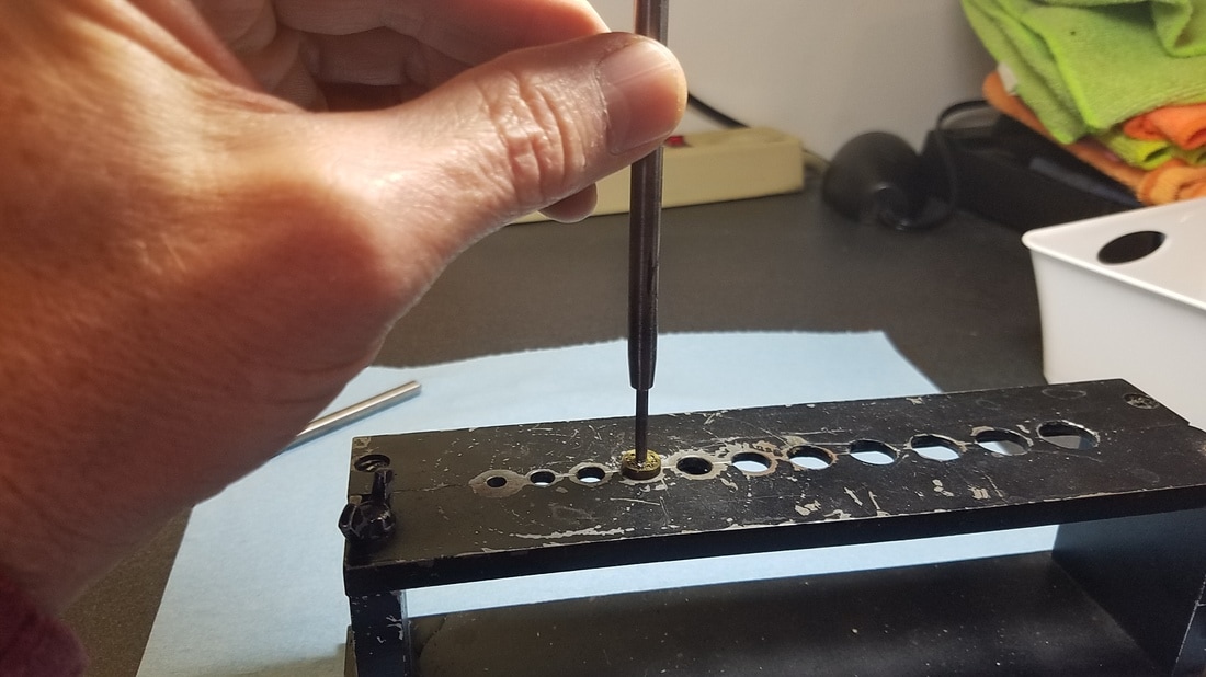
Using a hollow punch resting on the shoulder at the pivot to knock the arbor down and remove the shroud.
|
|
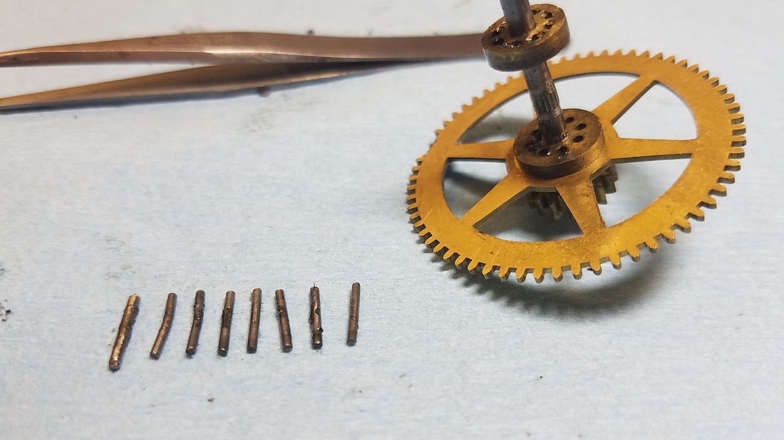
Trundles removed. There were 3 different diameters, a few were bent and there was a small amount of wear.
|
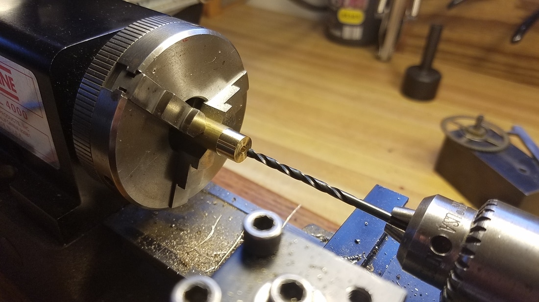
Starting to make the new shroud. I have it turned to the correct OD and I am drilling a slightly undersized hole for the arbor. The arbor is knurled where the shroud sits so I ended up having to enlarge the hole slightly with a broach when it was time to install it.
|
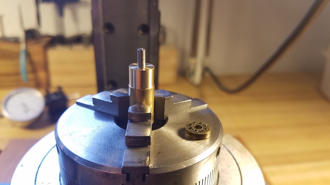
I thought the easiest way to find the location of the pitch circle was to turn a small post to temporarily put in the arbor hole so I could locate the old shroud directly over the new one I was making.
|
|
Here the old shroud has been placed on the temporary post and I am using a piece of music wire to locate one of the trundle holes. The music wire is what the new trundles will be make from.
|
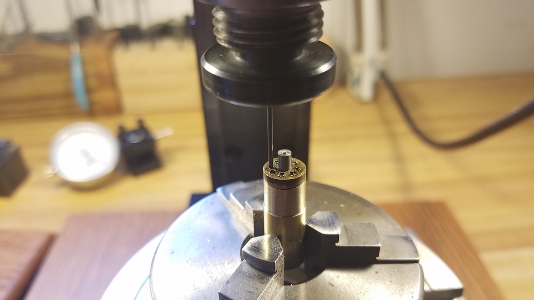
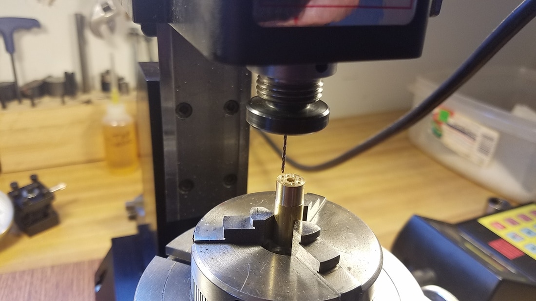
Once the first hole was located I removed the old shroud and used a spotting drill to mark each hole by using my CNC rotary table to index to each of the eight positions.
|
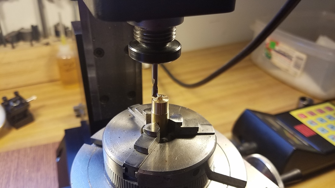
Then I drilled each hole a couple of thousands undersized then when I was finished drilling I used a homemade reamer to ream the holes to the exact size.
|
|
I moved the chuck back to the lathe after all the holes were drilled and parted off the new shroud. Then I started work on the tooth replacement.
|
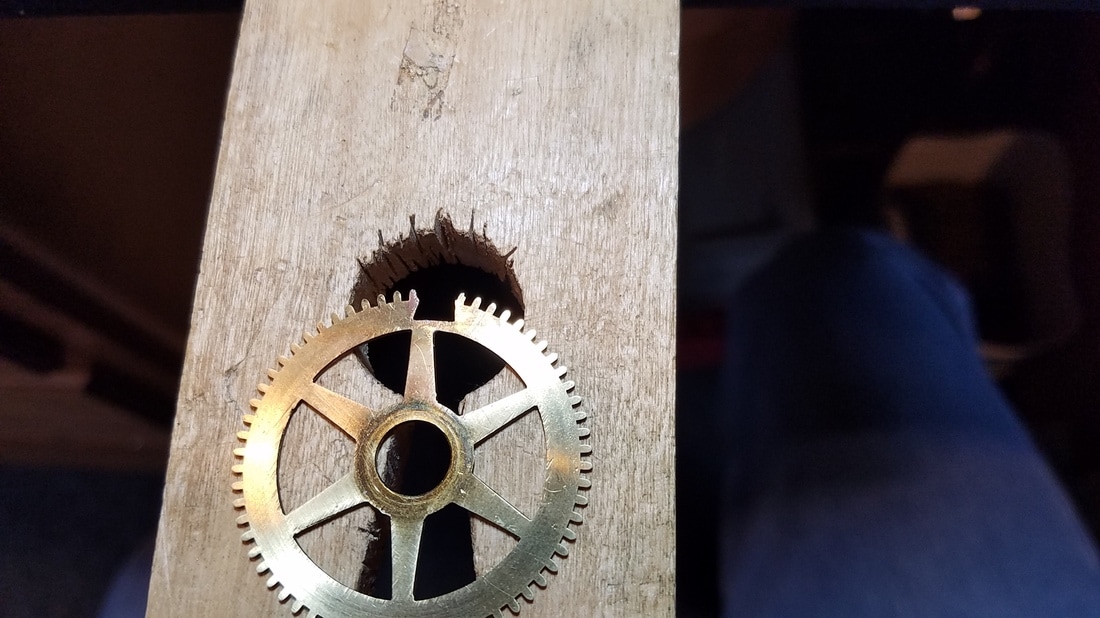
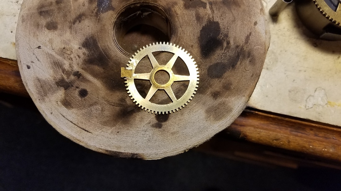
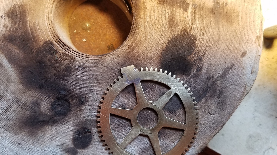
Here the old piece that had been soldered on has been removed and I had cleaned up the wheel. You can see the missing teeth on the right.
|
I thought the rest of the work would go easier if I removed the wheel from the arbor. Here I have used a jewelers saw to cut a dovetail where the teeth were missing. I found a scrap wheel of the same thickness that I cut out the blank that was used to fill this hole.
|
|
I about have the blank filed to size here.
|
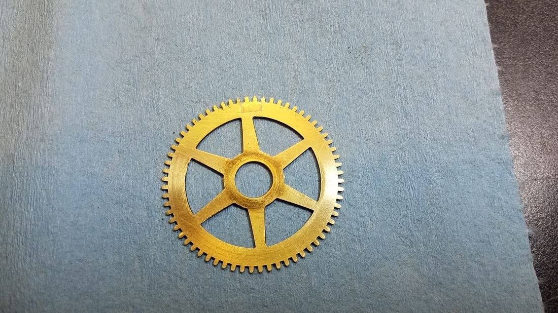
Finished filing to size and soldered in. I used Tix solder and flux for this. After soldering I used a scotchbrite pad and a small file to clean up the flux and remove the excess solder.
|
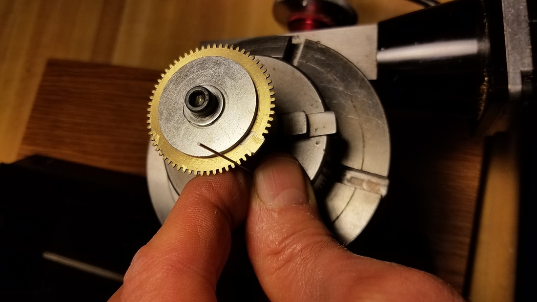
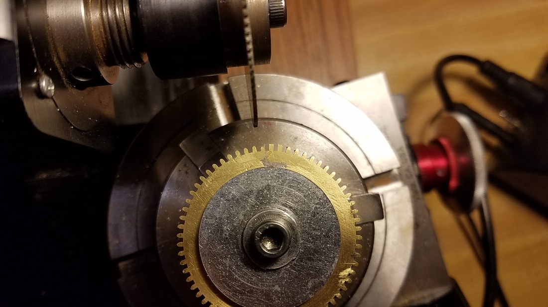
I mounted the wheel on a temporary homemade arbor I made so I could put it in a chuck. Then I put it in the lathe and turned it to remove the excess 'blank' I had soldered in. Now it is the same height at the rest of the teeth. I then moved the chuck and mounted it in my rotary table on my mill. Here I am measuring the distance between the teeth with a pin gauge.
|
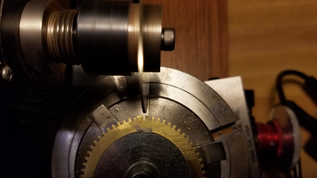
I had originally planned to use a single point cutter to cut the new teeth... that is why I went to so much trouble to mount the wheel on an arbor and put backing plates on both sides of the wheel for reinforcement which would not have been necessary if I had known I was going to use a slitting saw. Once I had the wheel mounted and ready to cut the teeth I tried each of the cutters I had previously made and none of them matched this tooth profile as closely as I had hoped. Since I only had a few teeth to cut I decided to simply use a slitting saw to cut the slot between the teeth and finish each of them off with small files. I didn't think it was worth the time it would take to make a new single point cutter to match this profile for just a few teeth. I used the pin gauge to determine the size of slitting saw I needed. In this case I used a .032 slitting saw. The wheel had 64 teeth and I set up the controller for my CNC rotary table for 64 divisions. Having the CNC rotary table to do all my indexing is some of the best money I have ever spent. In this case I only needed to make a few slots but I was assured they would be perfectly placed.
|
Starting to cut the new slots between teeth. I had first lined up the slitting saw to a good existing slot and zeroed my handwheel for the correct depth. Once all that was set the actual cutting went very quickly.
|
After slots had been cut.
|
Removed wheel from temporary arbor and started filing the tooth profile. Looking pretty good here but ended up doing a little more detail work later.
|
|
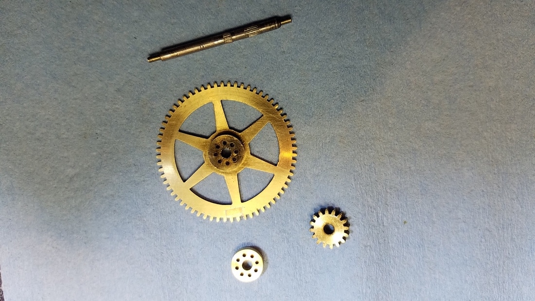
Here I have the wheel mounted back on it's hub which doubles as the lower shroud for the lantern pinion. The rest of the assembly is in this picture also. I had previously marked the location of where the hub was located radially in the wheel so I could maintain concentricity when reinstalled.
|
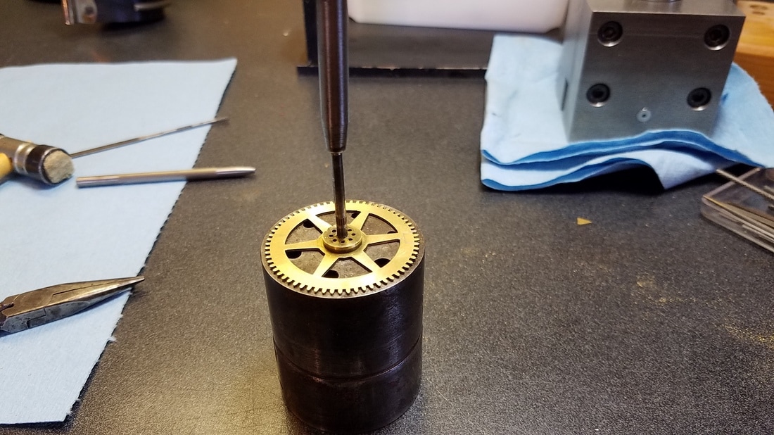
Using a hollow punch to push the arbor into the hub/lower shroud.
|
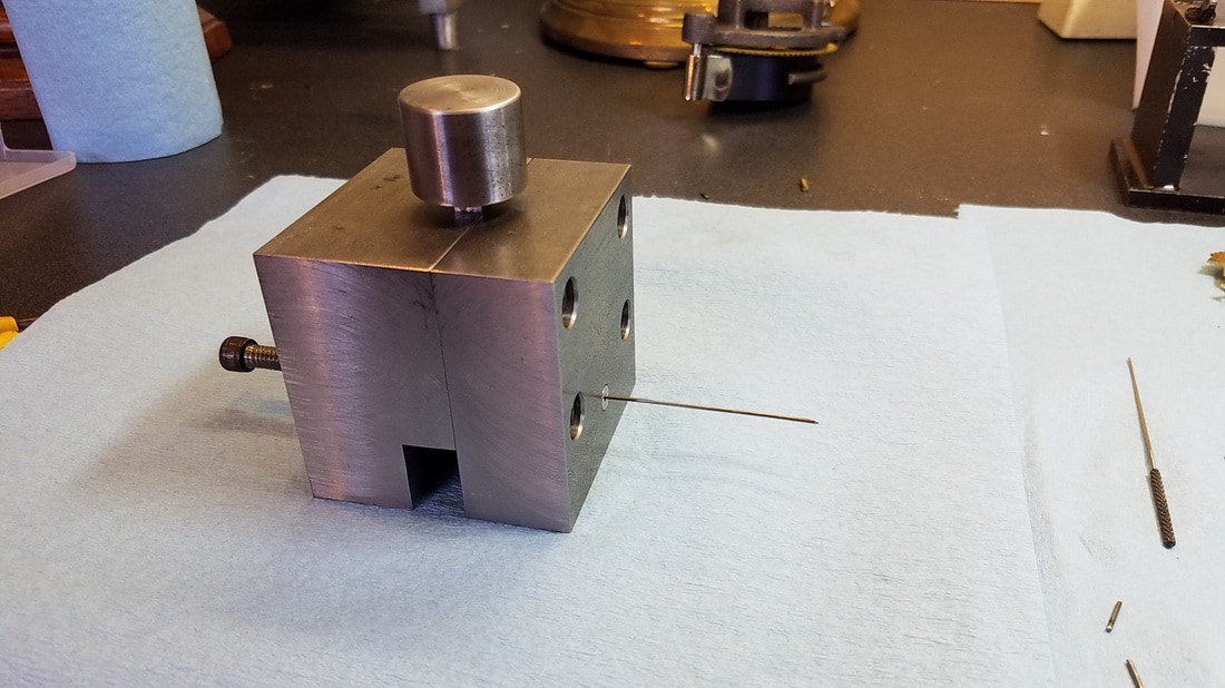
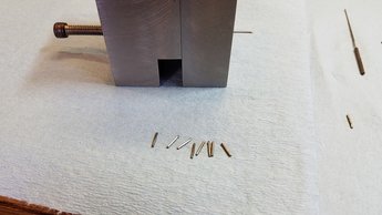
This is my wire shear. Under the large knob on the top is a 1/4 " HSS tool bit with a sharp cutting angle on it which works as a shear. It also has an adjustable screw on the far side which is used as a stop when the wire is fed in assuring that each cut will make the exact same length of wire. The wire is fed in from the right side until it hits the adjustable stop then the knob on top is pounded with a large hammer to shear the wire. I love this tool for cutting music wire/pivot wire when there needs to be several identical lengths cut.
|
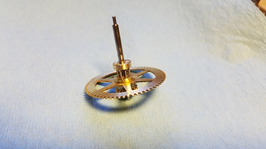
After all the trundles were installed I closed all the small holes in the upper shroud with a small punch. This is the finished product.
|
Shroud in correct position and now installing the rest of the trundles.
|

