Making a Junghans swinger Clock mainspring barrel
Click on any photo for a larger image.
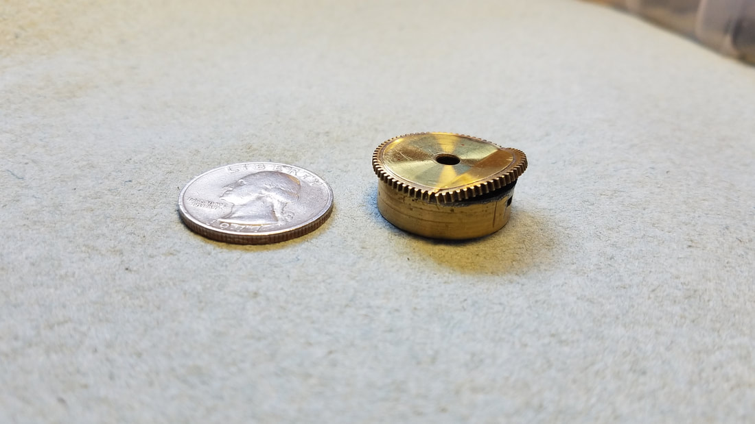
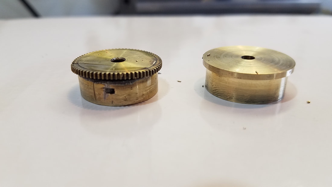
A customer recently asked me to make a new barrel for a Junghans Swinger clock. He had a mangled barrel he sent me to reproduce. The old barrel had a solder repair that had failed when the mainspring had let go and broken into 4 pieces and several teeth had been replaced. It was time for a new one. The Junghans barrel is small... less than 1 inch at the major diameter so I made the new barrel from 1" brass rod.
|
Old, mangled barrel. Cap and arbor have been removed and will be reused with new barrel. |
|
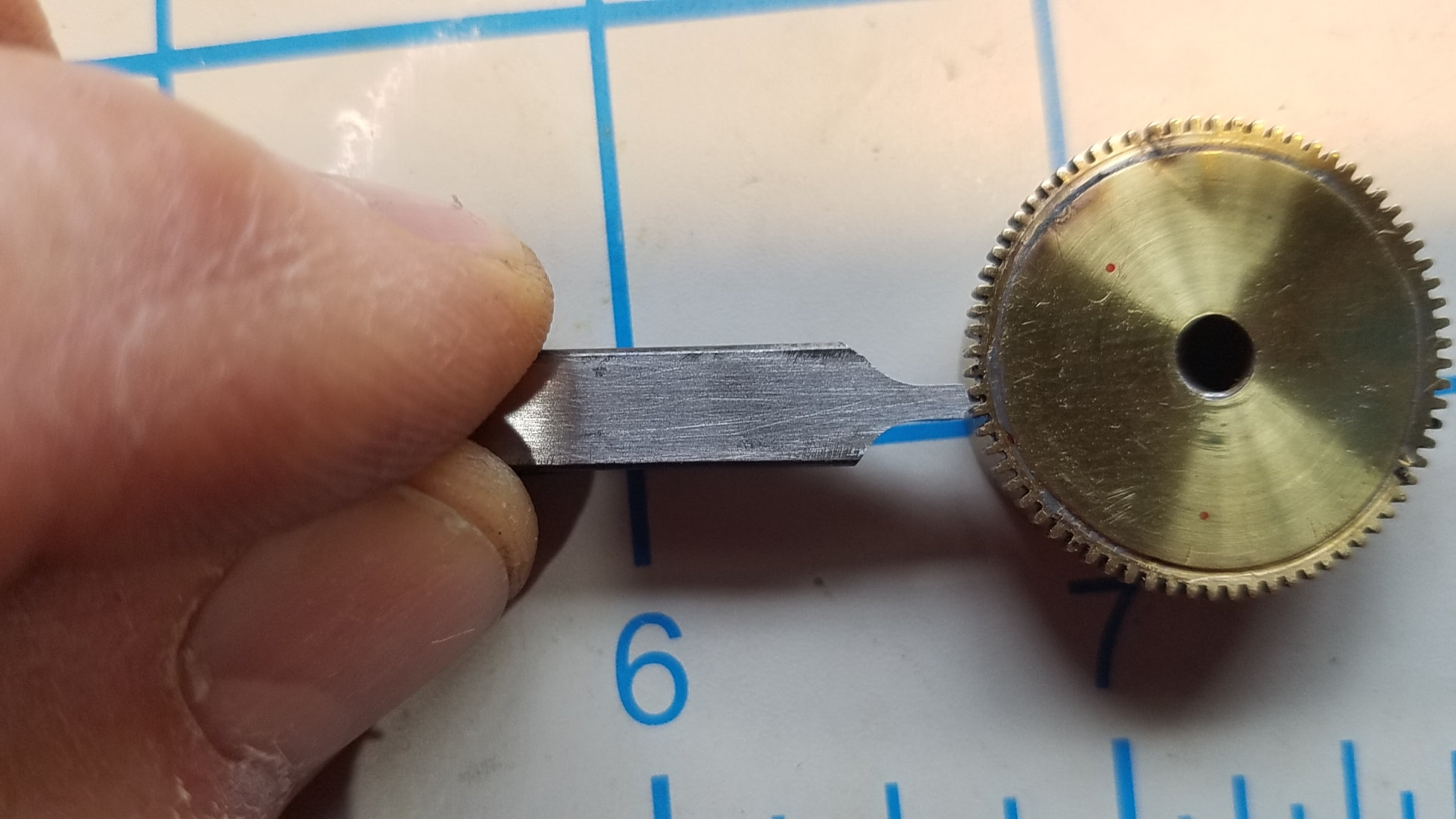
The first thing I did was to make a single point fly cutter that matched the tooth profile of the old barrel. For more details on how I made the cutter see my Repair Procedure for the Telechron Setting Gear, Page one. |
|
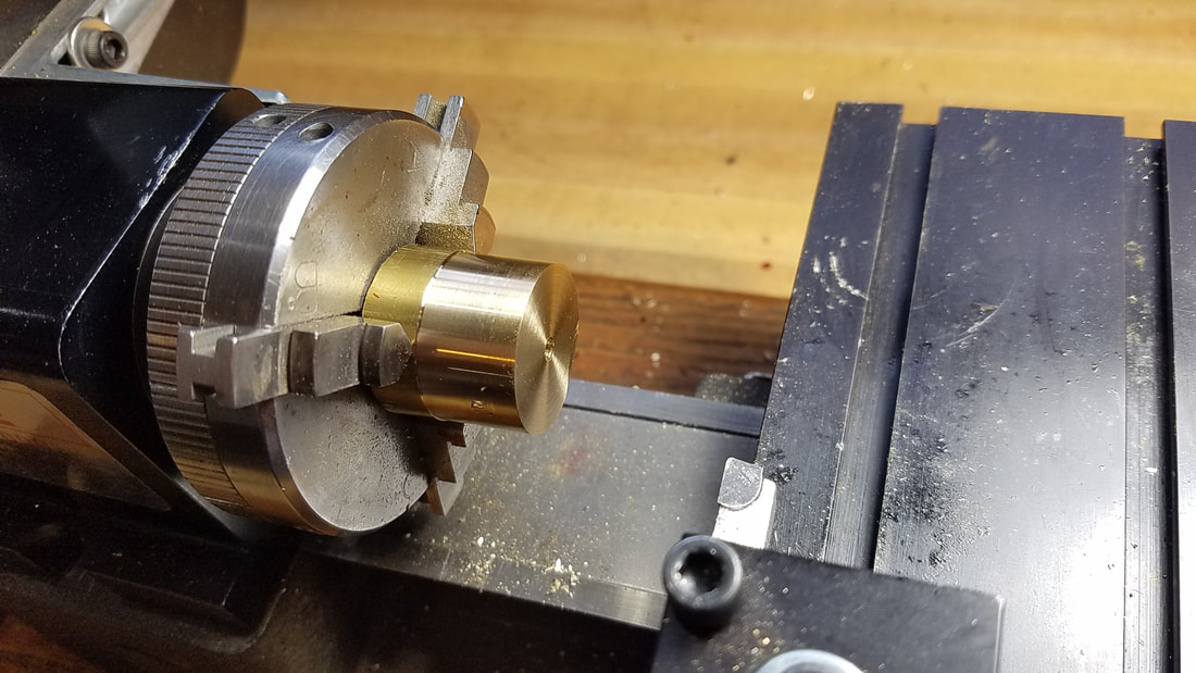
I cut off about 1.5" of 1" brass rod and put it in the 3 jaw chuck then turned to major diameter, faced off and drilled a hole all the way through. The hole size was just big enough for my smallest boring bar to fit in. I will increase the size of the hole to final diameter for the arbor later. |
|
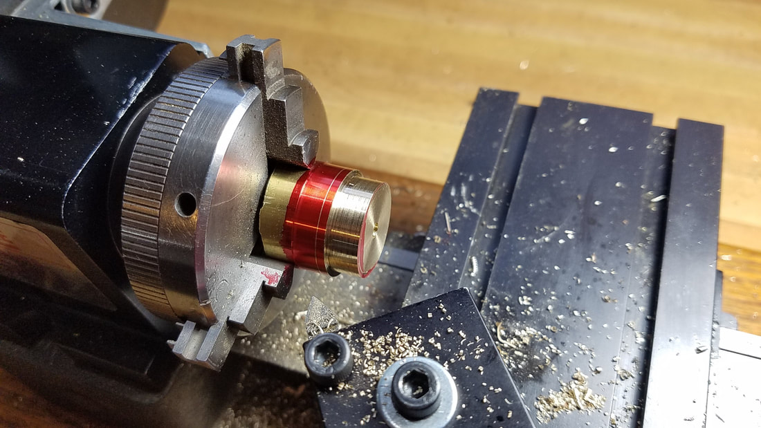
Using layout dye I marked the size of the sleeve and size of the gear. I have turned down the diameter of the sleeve portion here. |
|
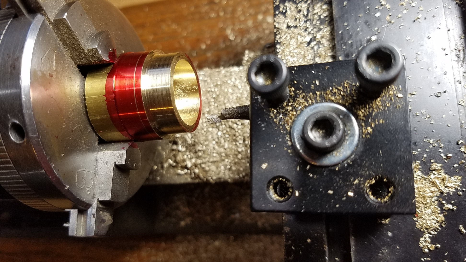
Boring the hole until I have the correct sleeve ID and depth. This was pretty slow going as the depth of the hole is actually deeper than the sleeve which leaves very little room for error on the depth. Also slowing the boring down is there is a raised bearing surface for the arbor bushing. It would have been much easier if the bottom had been entirely flat. In this situation it is critical to pay close attention to the handwheel settings and make sure you zero both axis before you start boring. |
|
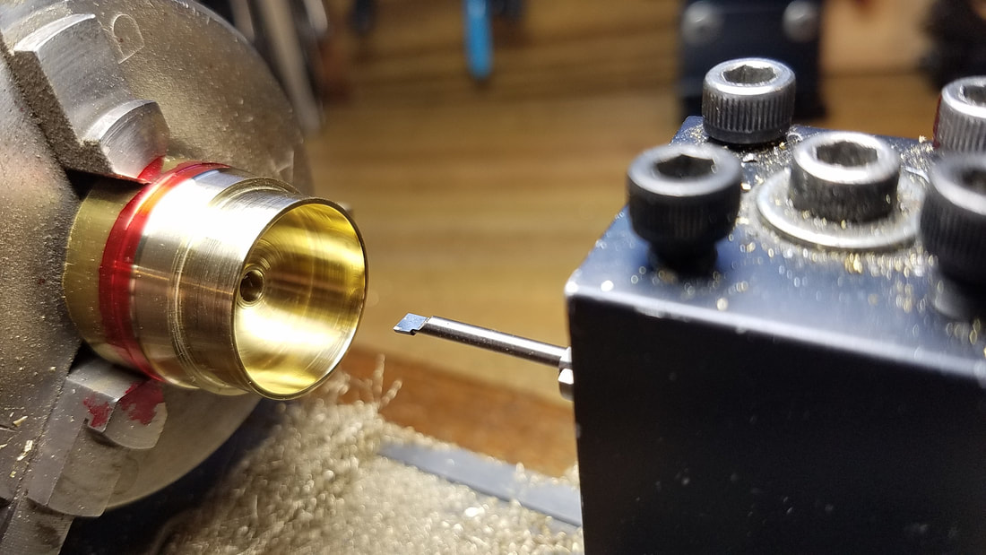
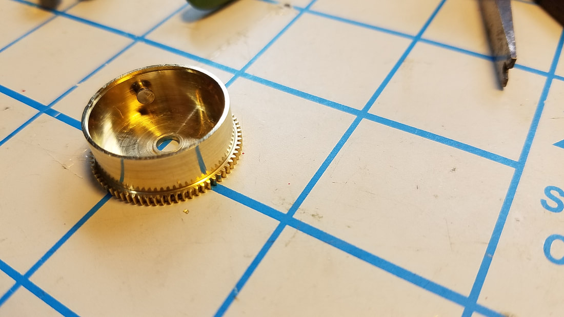
Here I have finalized the ID and if you look closely you can see the raised area around the arbor hole for additional bearing support. I also used a different boring bar to cut the groove for the cap. The groove has a slight bevel to ensure the cap pops in and stays securely in place. I also bored arbor hole to final size in this step. |
|
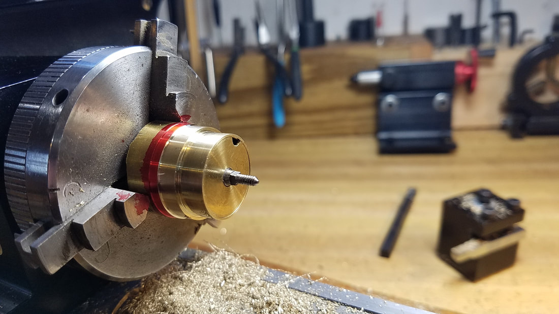
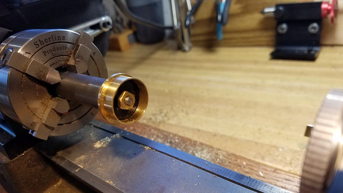
Testing the fit of the arbor and barrel cap. |
|
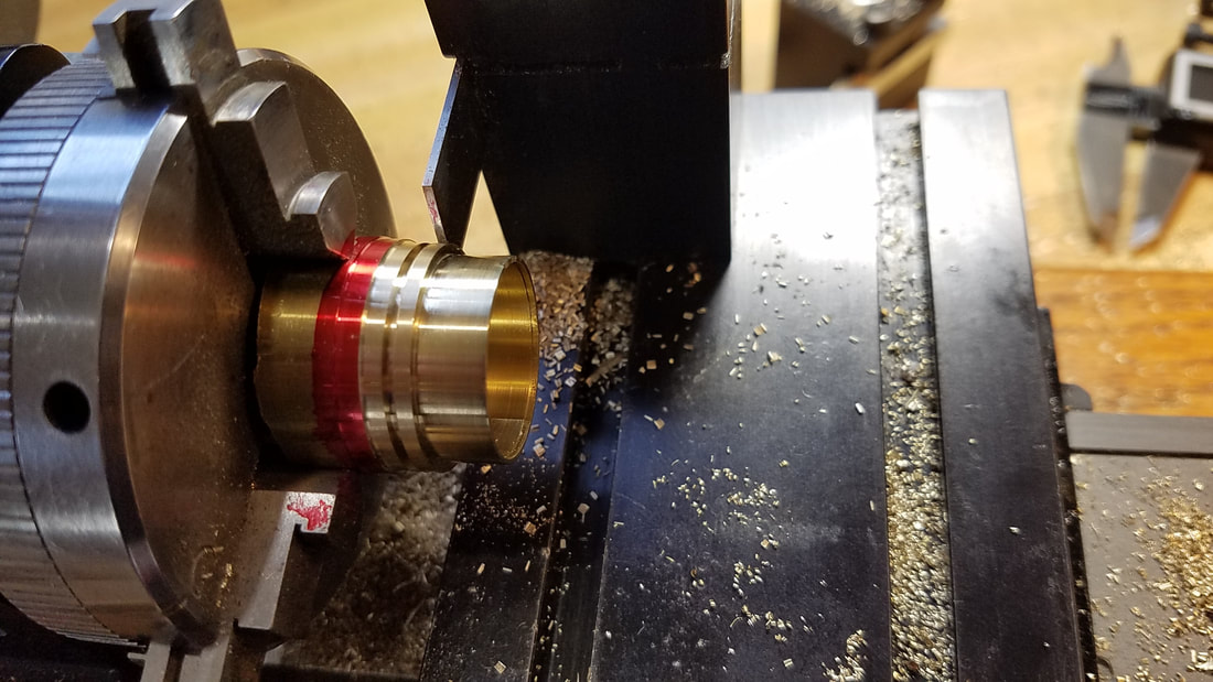
Parting off barrel. |
|
Ready to cut teeth. |
|
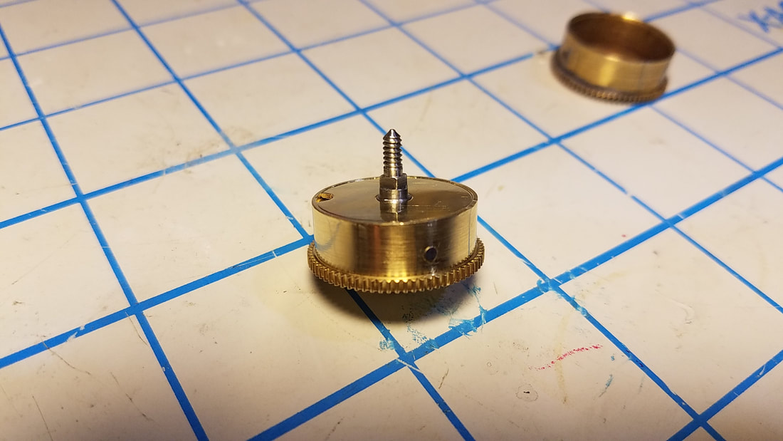
Mounted on a temporary arbor in a 4 jaw chuck for teeth cutting. I turned a piece of black delrin to fit below the nut for stability. |
|
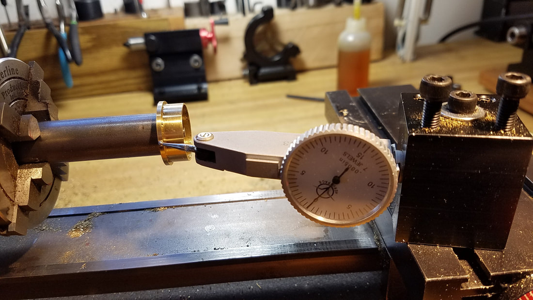
Using a test indicator so I can adjust 4 jaw chuck for zero runout. I can mount my 4 jaw chuck on the rotary table of my mill but I can adjust the runout easier on the lathe then move chuck to the rotary table. |
|
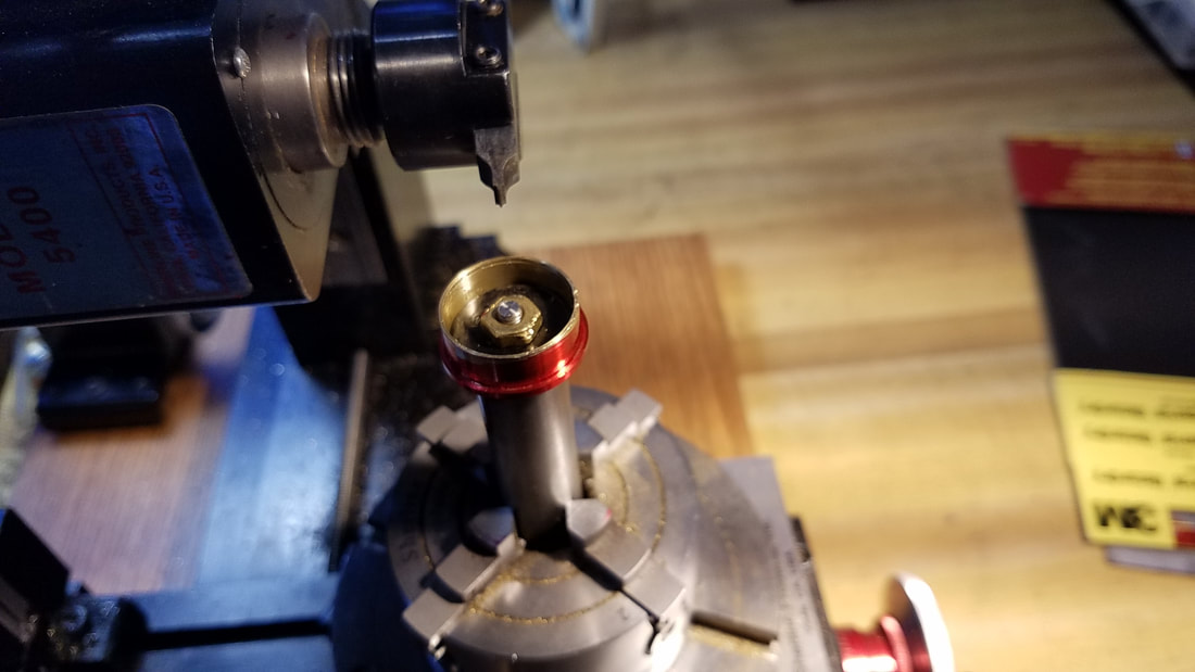
I have the milling spindle turned to the horizontal position and now the 4 jaw chuck is mounted on the CNC rotary table. I do not show setting the center of the cutter to the center of the barrel but it is a very important step else the teeth will lean to one direction. |

|
CNC rotary table is set for 72 divisions and now starting to cut the teeth. Once the correct depth of the first tooth is set then I lock both axis of the table and simply run the Z axis up and down for each division. All 72 teeth took about 20 or 30 minutes. |
|
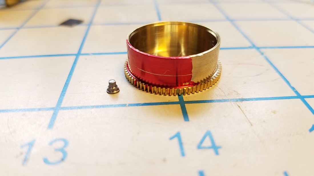
Finished cutting teeth. Marked with layout dye to locate hole for barrel hook. Notice the hook I machined sitting next to the barrel. For more info on how to machine and install a barrel hook see my Repair Procedure for Barrel Hook Replacement. |
|
Barrel hook riveted in place. |
|
Barrel assembled with new mainspring. I used the original barrel cap and the original arbor. |
Thanks for looking. Feel free to contact me for more details about making a clock mainspring barrel. Also contact me if you need any type of barrel machining or a complete barrel fabricated.
