Building an American Clock Movement

I have been repairing clocks for about 25 years but this was my first attempt to make a movement. I used the book 'Building an American Clock Movement' by Steven Conover. The book is very good for a first time clock build . I am combining techniques from the book with some NAWCC training I have recently taken taught by Jerry Kieffer. I am using his procedure to cut my wheels including making the single point cutters used to machine the teeth. Below is an image diary of my progress.
Click on any image to see a full size picture.
Click on any image to see a full size picture.
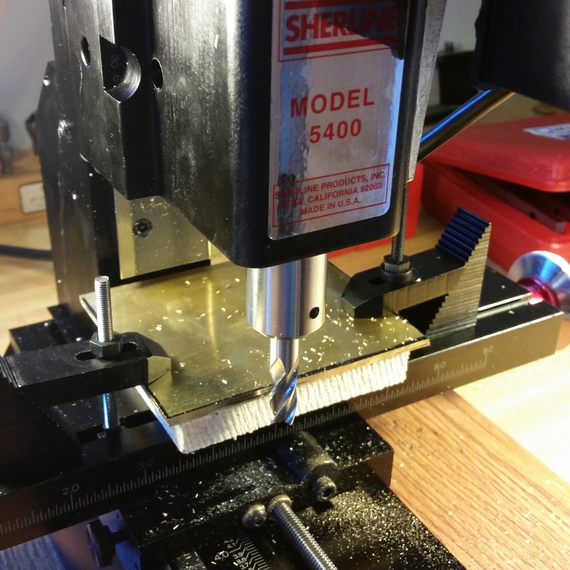
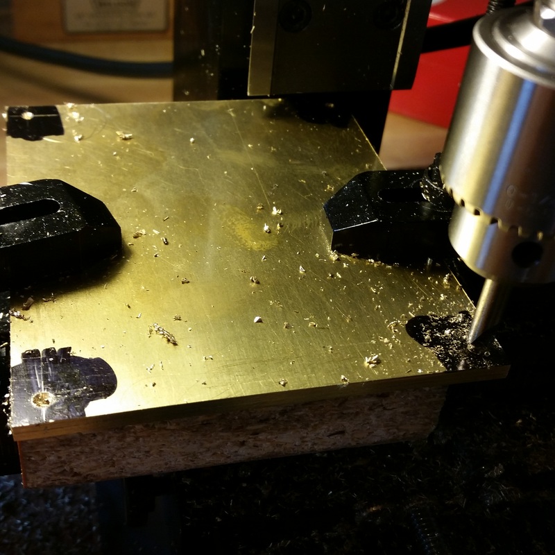
After cutting out the plates I clamped both plates together in the mill and used an end mill to finish all the edges to dimension.
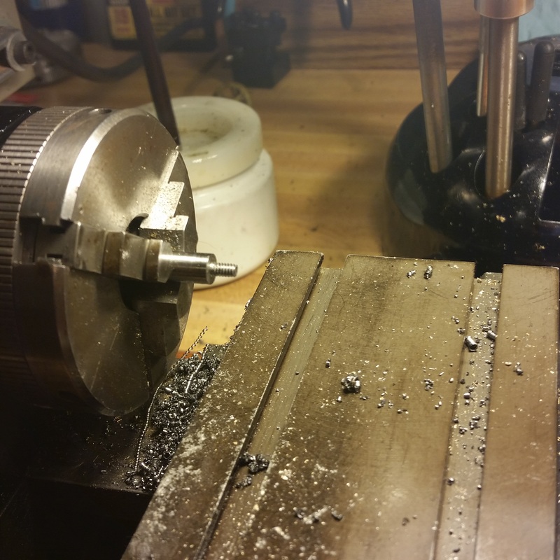
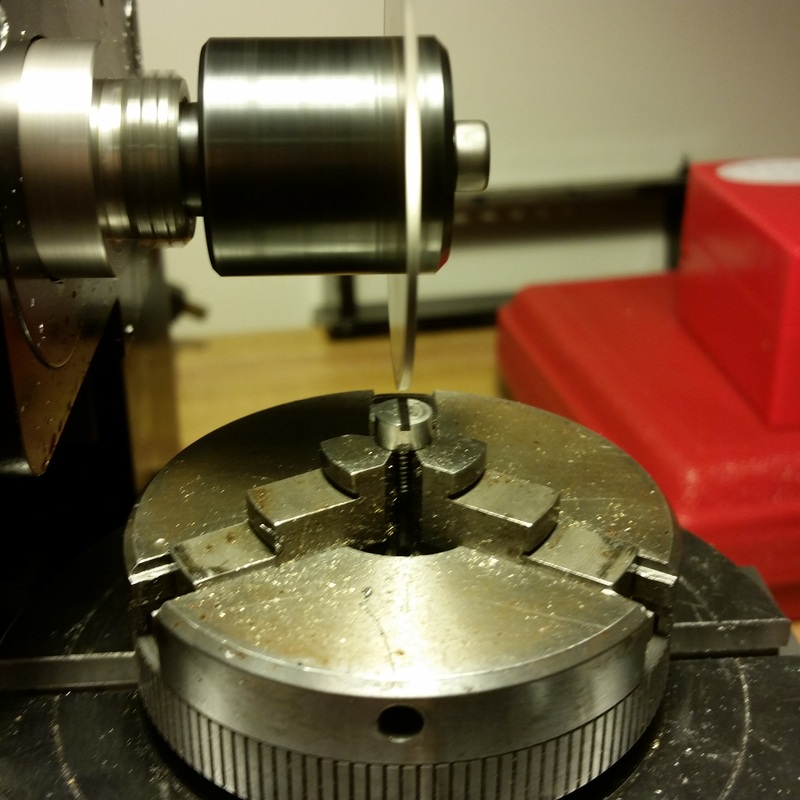
Making the pillar screws.
|
|


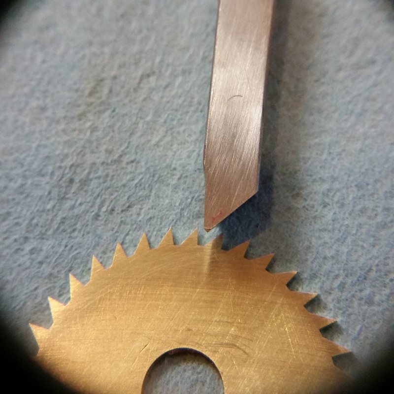
Using a single point cutter and a rotary table to cut teeth.
|
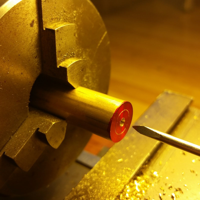
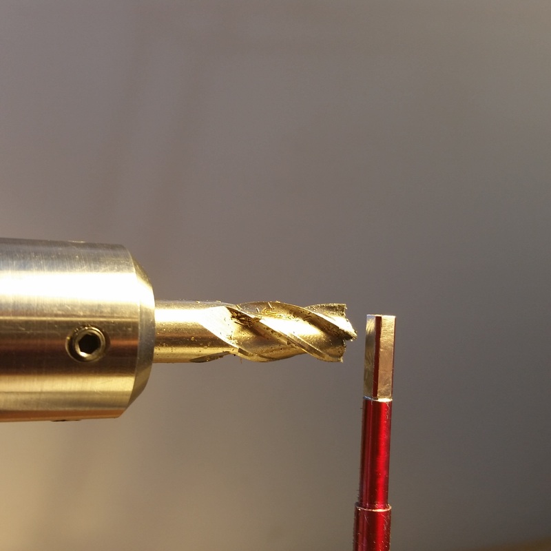
Starting on my first lantern pinion. I have the pitch circle drawn and the hole is already drilled a few thousands undersized. I am getting ready to ream out the hole to the final size with a homemade reamer made from music wire. Since the arbor will be made from the same size music wire this made a perfect slip fit.
|
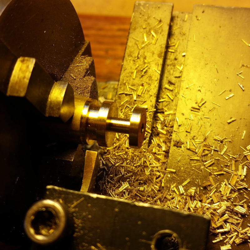
Machining the body of the pinion with a tool I ground.
|
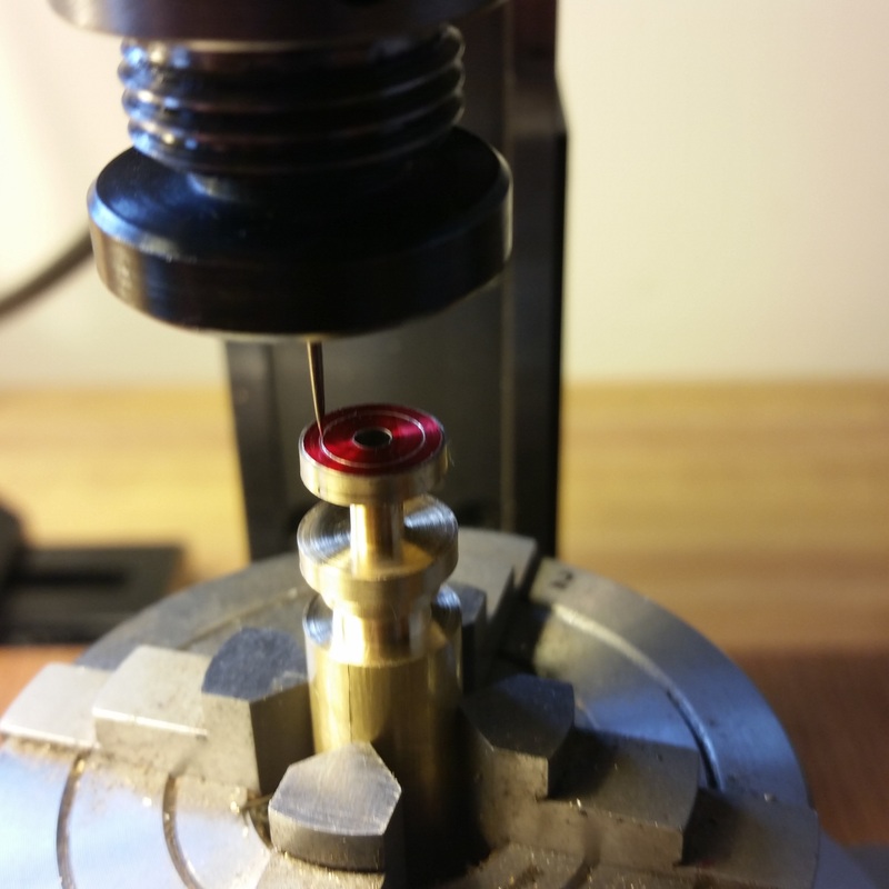
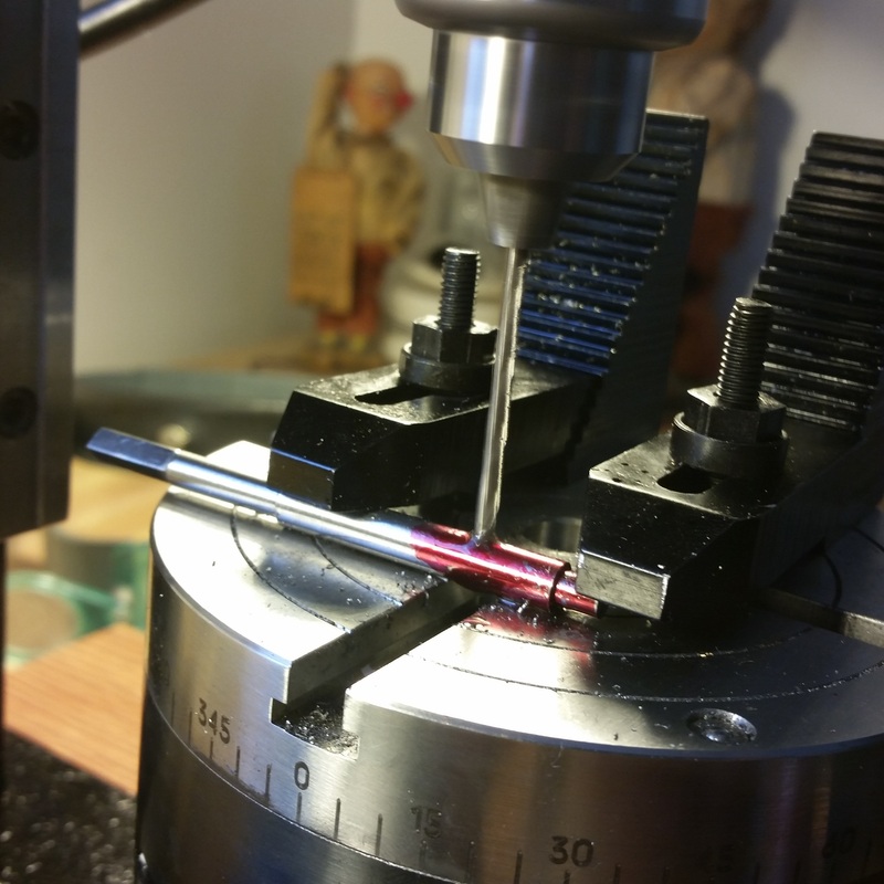
Setting up to drill the trunion holes using a rotary table. Here I am locating the mill head to the pitch circle using a sewing needle in a WW collet,
|

Using center drill to start the holes.
|
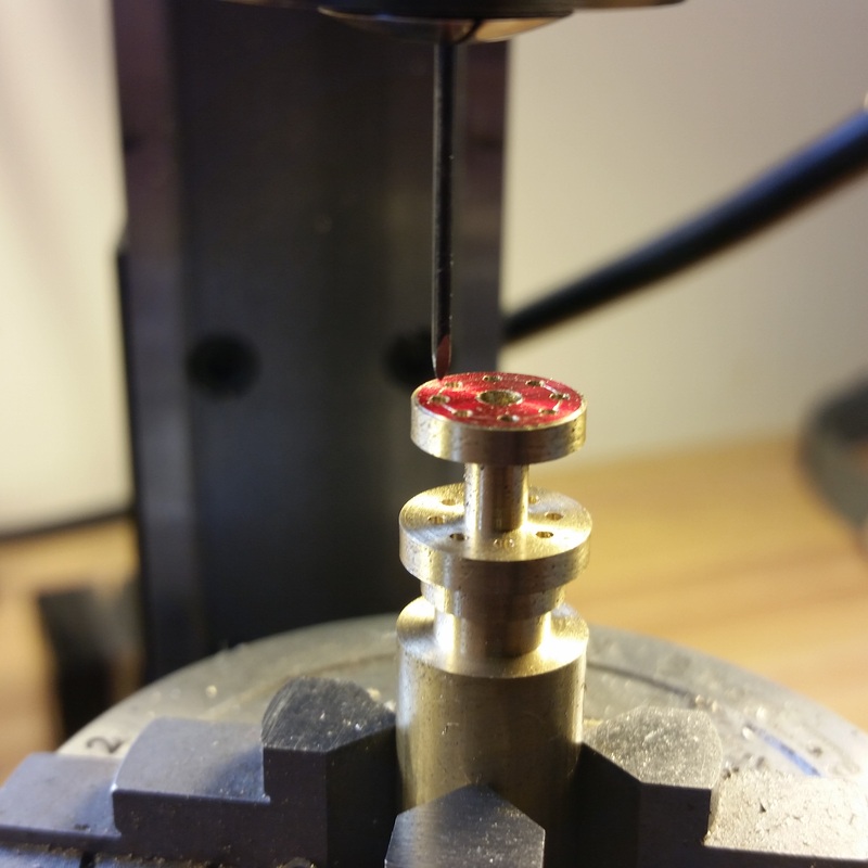
All holes drilled undersized again and getting ready to use another homemade reamer to open the holes to the trunion size.
|
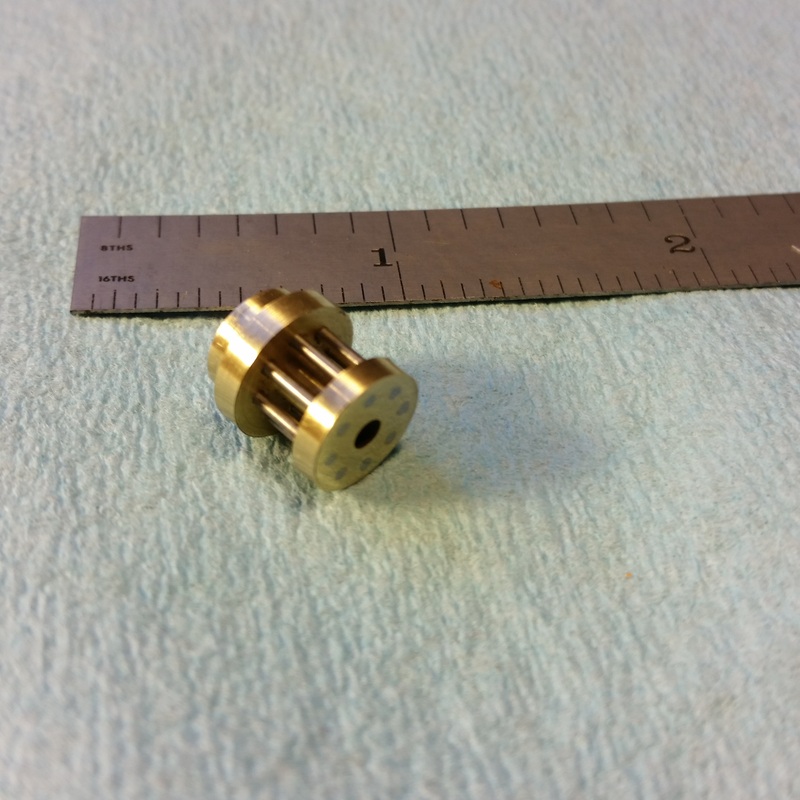
Finished lantern pinion.
|
|
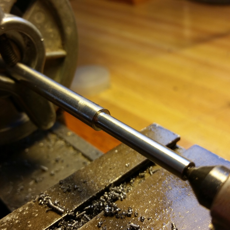
Cross drilling main arbor for mainspring hook.
|
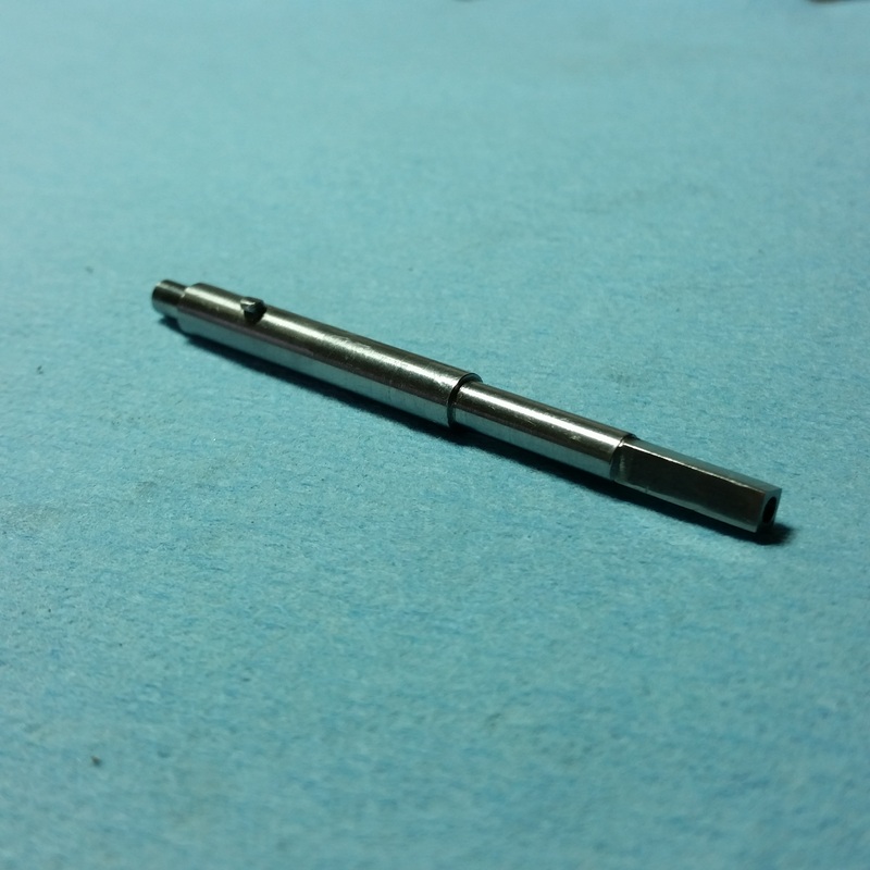
Finished main arbor.
|

I am getting ready to make a flat depthing tool but wanted to know how well my wheels and pinions worked so I used a small vice with some music wire for arbors in it to test my fit. It was difficult to get the depthing just right using the vice but once I got it my wheels and pinions ran very smoothly. I plan to make the depthing tool soon. The piece below the pinion is a piece of scrap brass that I am using as a spacer here, it is not part of the pinion.
|
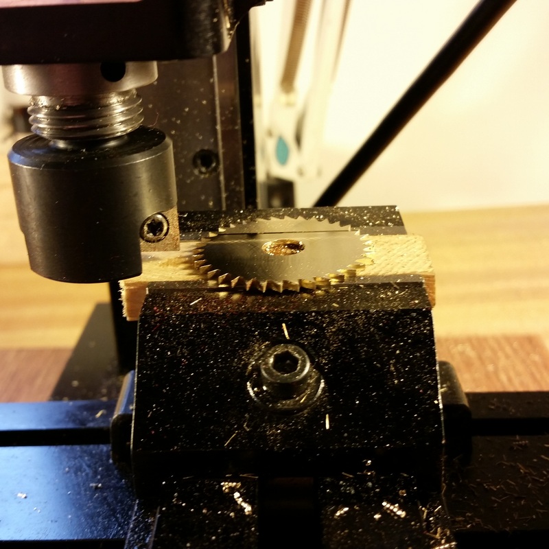
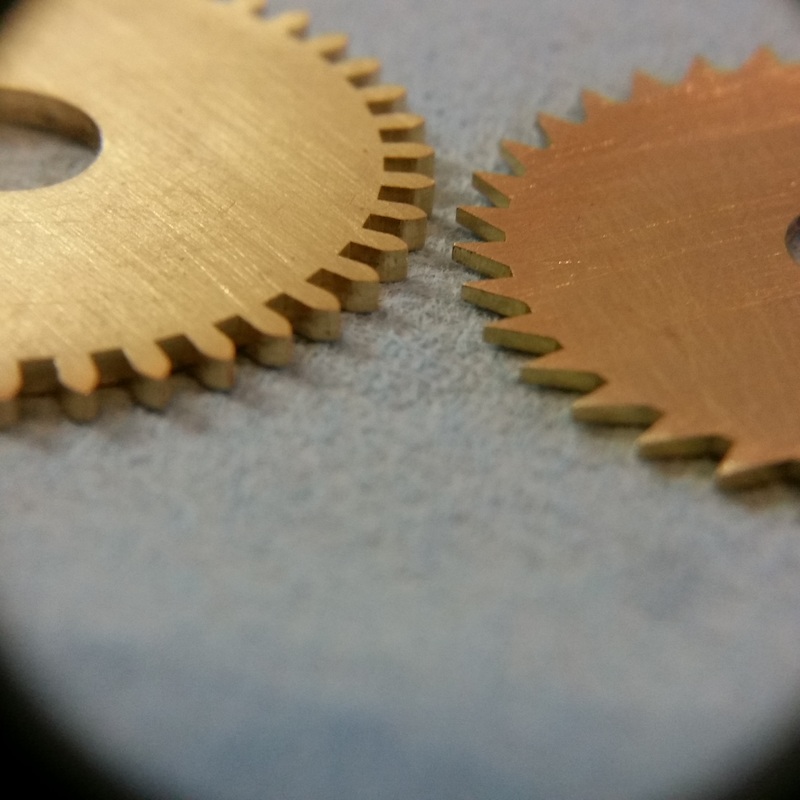
The escape wheel is designed to be half the thickness of the other wheels and I didn't want to buy a sheet of brass just for the one wheel so I cut the wheel from the same material as the other wheels then I super-glued the wheel to a small piece of wood then mounted in the mill vice to use fly cutter to cut to dimension. I had no idea how well this would work but it worked great. Since the wheel is wider than the piece of wood I could ensure the wheel was perfectly flat against the machined vice jaws before I tightened it. When I was done cutting the wheel was within .002 thousandths of being perfectly flat. If I was going to do this again I think I would fly cut the escape wheel blank to thickness before I cut the teeth. The fly cutter left small burrs in the teeth. They were easy to clean up but I still think it might be wise to reverse the order.
|
|