This page will show how I used the single point cutter made on the previous page to cut the teeth for a new winding gear in a Telechron wall clock.
Click on any photo for a larger image.

The OD of the new gear is about .320" diameter so I chucked up a scrap piece of 3/8" steel I had in the junk drawer. I believe it is 12L14 which is not ideal for making a steel pinion but I think it will work great for a winding gear on a clock that will only be used when changing the time on the clock. I wanted to make the entire assembly (shaft and gear) one piece so that is why I have such a long piece chucked up. I started by turning the area of the gear down to .320" then cutting away most of the shaft near the gear so when cutting teeth the cutter would not have to do any unnecessary cutting. I left the gear portion about twice as thick as the actual gear for added strength while cutting and I left the shaft a larger diameter than needed for the same reason. Both of those would be machined to the correct dimensions after the teeth were cut.
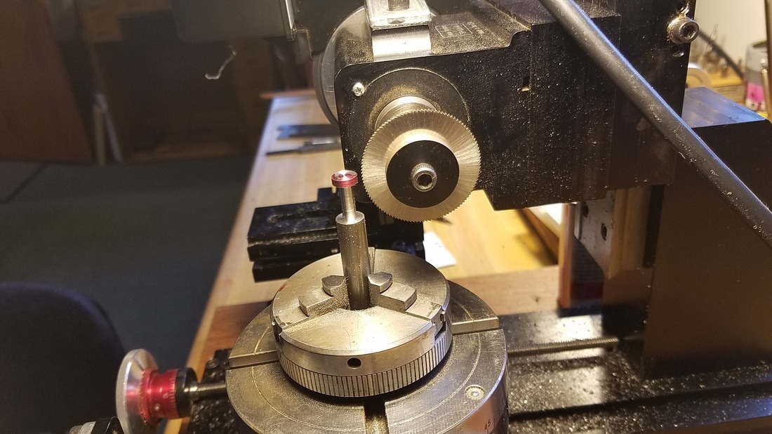
I then moved the chuck with the gear in place and put it on the rotary table that was clamped to the bed of my mill. I turned the mill's spindle horizontal and put a .025" slitting saw in the saw holder.
I used the slitting saw to hog out as much of the metal between the teeth as I could. Any less metal for the homemade single point cutter to to cut out the better chance it would stay sharp and not chip. My rotary table is CNC controlled so I simply told it that I wanted 11 divisions then found the center of the gear with the slitting saw. I set the Y axis to cut about .060" deep and then used the Z axis running the saw through the gear at each of the 11 stops.
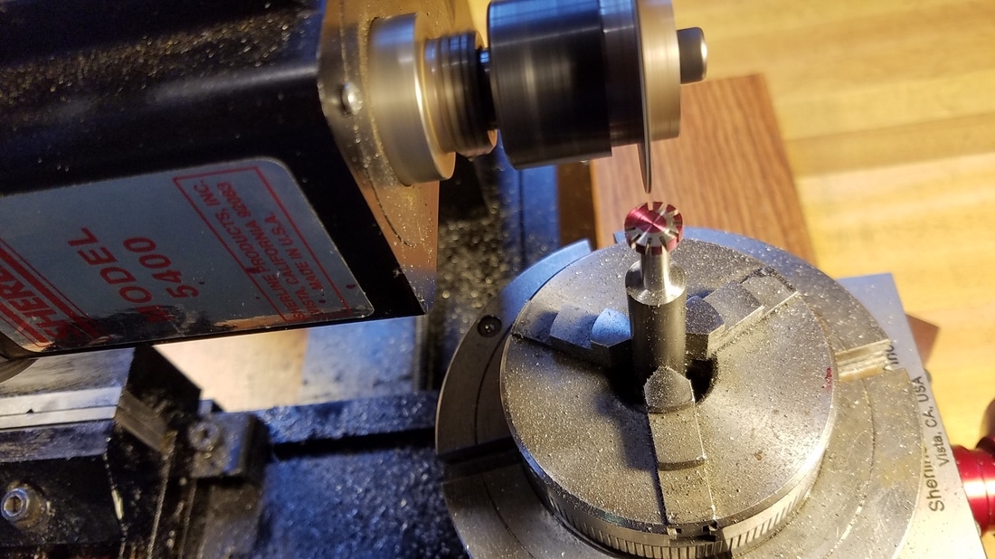
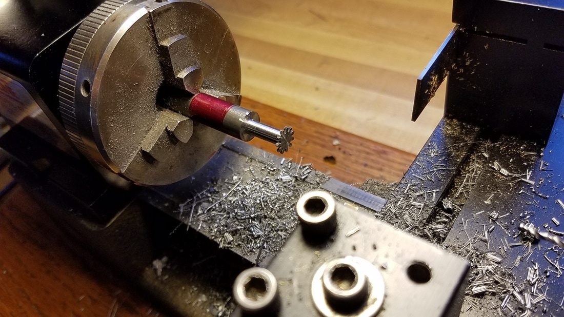
Here I am finished with the slitting saw and have installed the new homemade single point cutter into the holder. I had to adjust the Y axis so the cutter was centered on the gear. This time I made a few passes at each division increasing the depth each time and watching to see when the tooth profile was complete. |
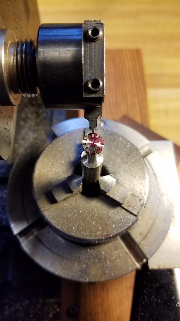
This picture shows the gear with all of the teeth cutting finished. The homemade cutter looked just as sharp when I was done as when I started. |
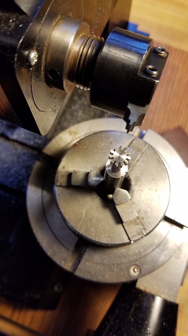
Now I moved the chuck back to the lathe to finish machining the shaft and also face the gear down to the correct thickness.
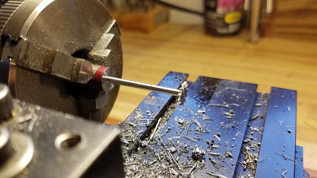
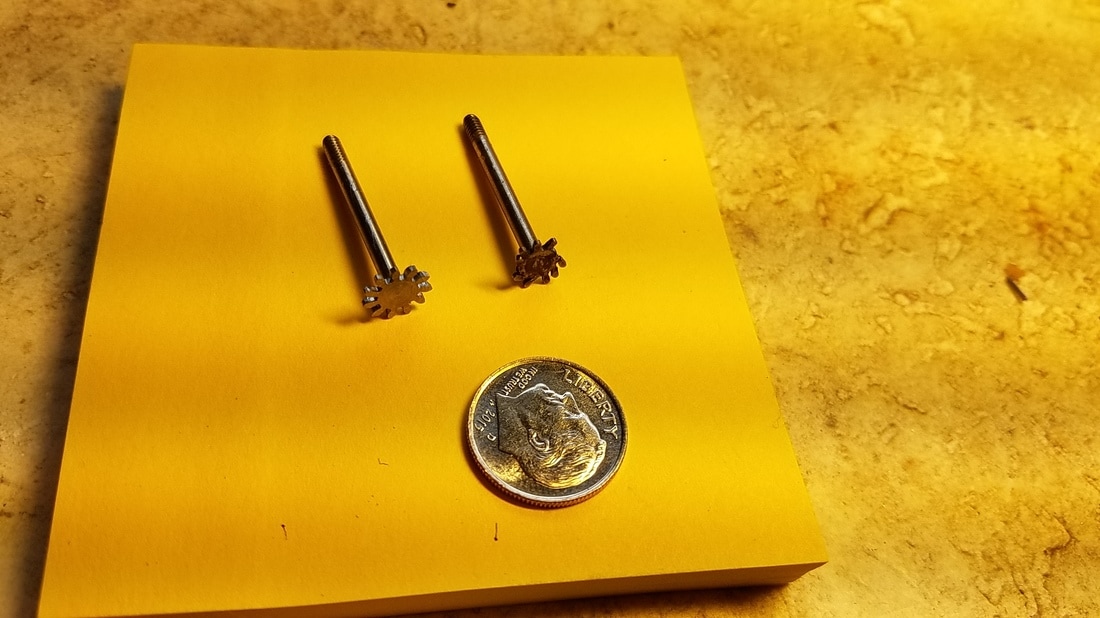
All the machining is finished here and the gear and shaft are ready to part off.
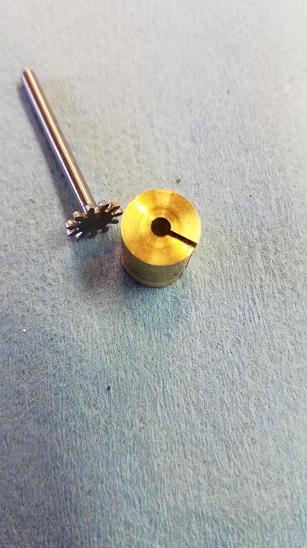
The only thing left to do was to thread the end of the shaft. I made the split brass bushing in this photo to hold the gear and shaft in the 3 jaw chuck while I used a 3-48 die to cut the threads on the end of the shaft. |
|
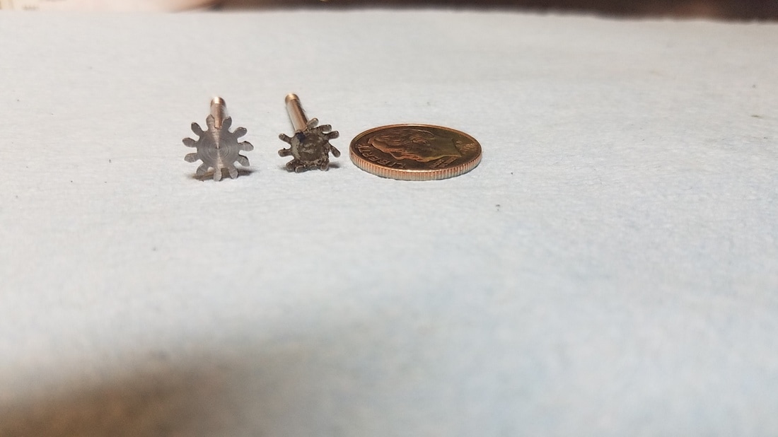
I hope that I was able to show this in a way that was easily understood. If anyone has any questions feel free to email me with the info on my contact page.
