This page will show making a single point cutter to machine the gear shown below.
Page 2 shows how I used and indexed the cutter to machine a new shaft and gear.
Page 2 shows how I used and indexed the cutter to machine a new shaft and gear.
Click on any photo for a larger image.
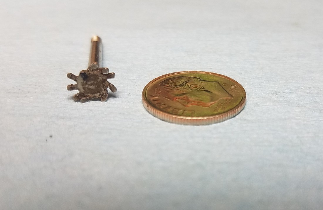
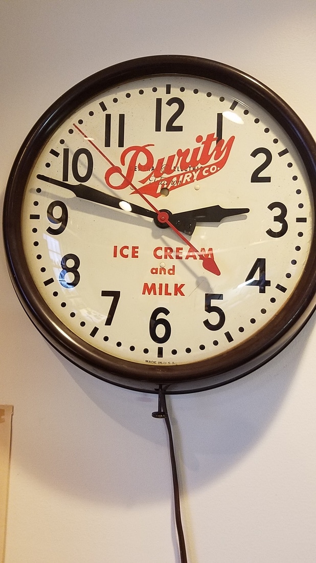
I recently decided to work on an electric wall clock that has been hanging on the wall in my clock shop for 20 years. It was a family clock but had not been in running order since I acquired it. Among the problems I found when I took the movement apart was this gear was bad. It is the 'setting gear' and it is what is used when setting the time. The gear had 2 teeth missing and all the others were bent beyond repair. I decided to document the procedure of making a new gear because a few people that have seen the clock movement I built have asked me how I made the clock wheels. I used the same basic procedure to make this gear as I did when I made the wheels in the clock movement I built. The biggest difference was that this was the first steel gear that I have attempted to make. I will try to show step by step how I made the cutter and cut the teeth. Credit for the procedure to make the single point cutter and the method to cut the gear goes to Jerry Kieffer, the instructor at the classes I attended at the NAWCC (National Assosiation of Watch and Clock Collectores) school of Horology in Columbia PA. In this case the gear was so mangled that I knew there would be some guess work involved in getting the correct tooth profile transferred to the cutter. Normally I have used Malcomb Wild's book on clock wheel cutting to calculate the correct module and to find the tooth radius but this appeared to be a modified tooth profile so the tables in the book were not much help. I tried to pick the two best teeth that were adjacent to each other to measure distance between the teeth... in this case it was .035". The tooth height was .065" and the tooth width was about .030". There were 11 teeth and the OD of the gear was about .320". I decided that I would make the gear and the shaft all one piece.. this actually made the job easier and guaranteed the gear would be concentric with the shaft. Once I started maching the gear and shaft it never came out of the 3 jaw chuck until it was finished. All of the machining was done on a Sherline lathe and mill with common Sherline accessories. I used a Sherline CNC rotary table to index the gear when cutting teeth. |
|
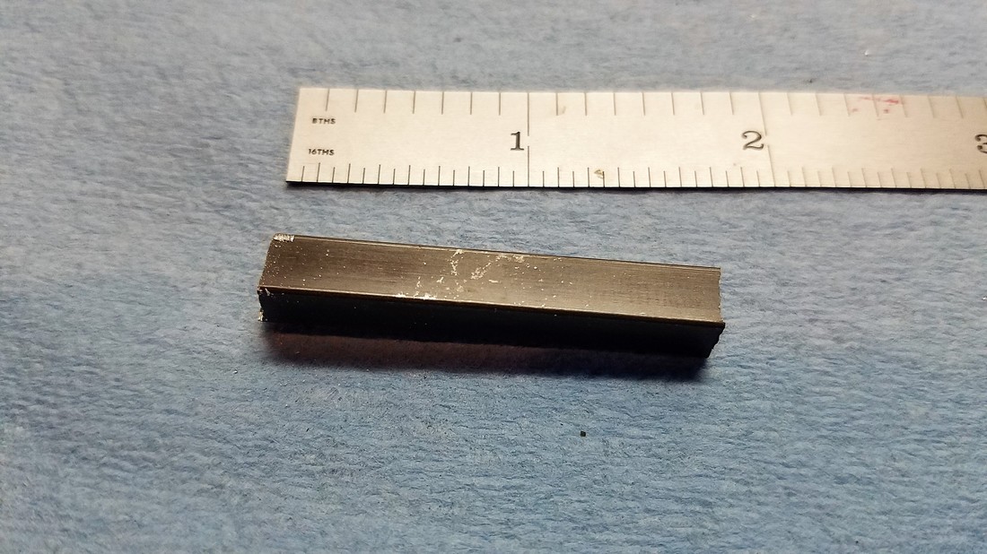
The single point cutter is made from .250 square W-1 tool steel. I bought a couple of 3 foot pieces of the tool steel so the first step is to cut off about 1.5 inches... a hack saw works fine.

I mounted and squared the milling vice on the mill table and used a parallel to ensure the blank was square in the vice. |
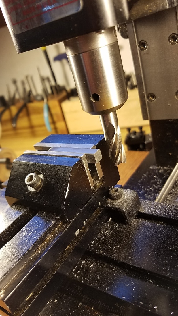
Then used 3/8" end mill to square the ends of the blank. |
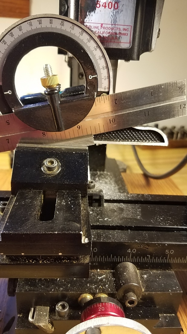
Now the blank needs to be mounted in the vice at about a 15 degree angle before making the first cut. This is how I measured the angle. |
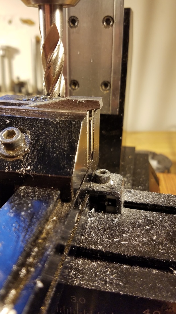
Use the same 3/8" end mill to mill the top of the blank cutter on the right hand side until the end is reduced to about .125". |
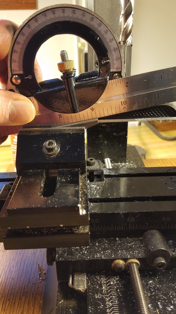
Now flip the blank cutter over in the vice keeping the milled end on the right hand side and set the angle to about 10 to 12 degrees as shown. |
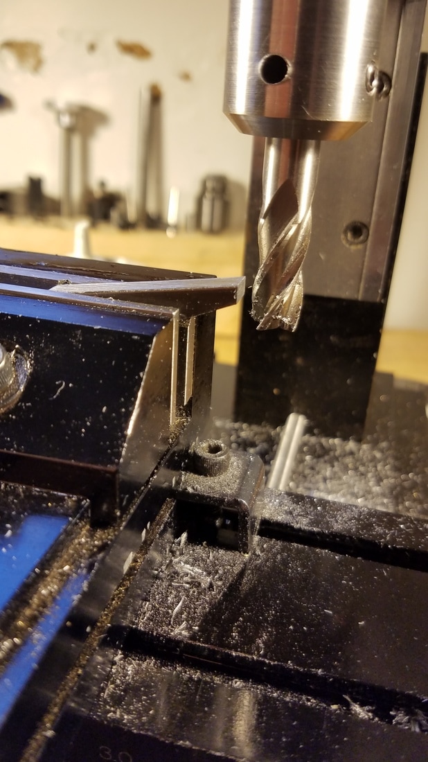
Using the 3/8" end mill square the end of the blank at 90 degrees to the mill as shown. |
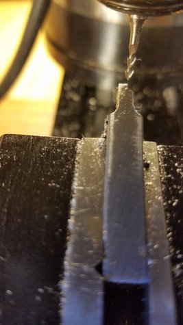
To make the next cuts a 3/16" end mill is used. Once the new end mill was installed I adjusted both the X and Y axis to zero. The X axis is adjusted to zero when the end mill is just touching the front of the blank cutter and the Y axis is adjusted to zero when the end mill is just touching the right side of the blank. Be aware of backlash and only adjust the zero's after moving the table toward the end mill, if you find it necessary to reverse the direction of the table before you set the knobs to zero then you will need to start over. Setting these zero's is critical to making a single point cutter with the correct tooth profile. I do it with the mill running at a slow speed and very slowly move the table toward the end mill until I hear it start to cut and then shut off the mill and adjust my zero.
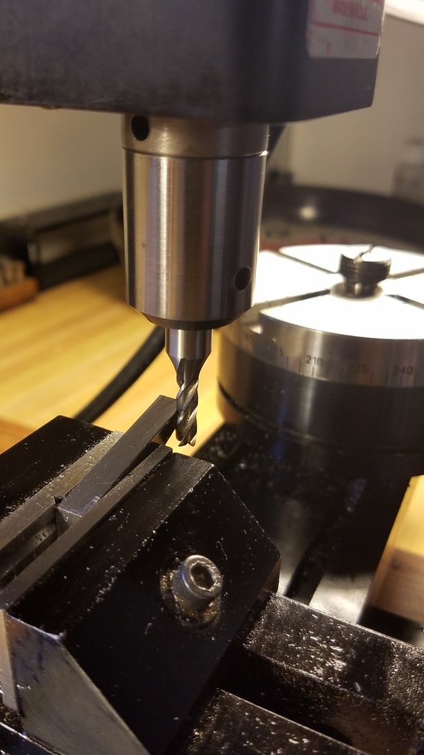
This shows setting the Y axis zero. (no photo showing setting the X axis to zero) |
|
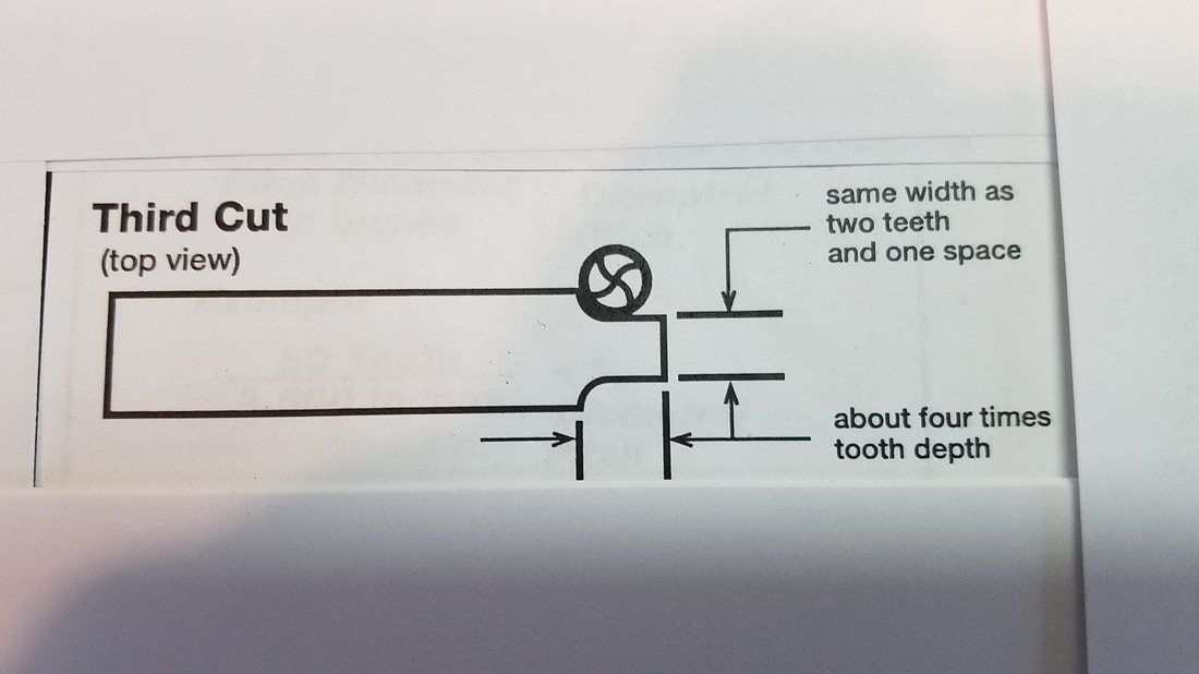
Refer to the pictures from Jerry's classroom handout for view of next cuts. The 3rd cut is done next with a 3/16" end mill . The dimensions for these cuts will be determined by the wheel or gear you are making. In my case I needed to remove equal amounts of metal from the front and back side so I would be left with a width of .095" (same as the width as 2 teeth and 1 space). The distance from right to left that I would remove material in my case was .260" (4 times tooth depth).
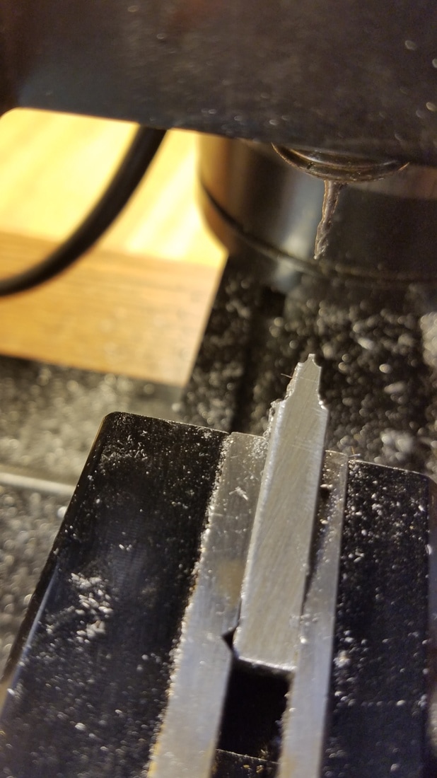
This shows what my cutter looked like after making the front cut. The blank is .250" wide and I needed to remove enough material to end up with .095" but I need to take equal amounts off the front and back side keeping the end of the blank centered so I needed to remove a total of .155". I divided that in half (.0775") and took that amount off both the front and back sides of the blank. |
Top view of what the cutter blank looked like after I was finished with the 3rd cuts. Note: Both of these cuts were made in 2 passes each as I thought it was too much material to cut in one pass. |
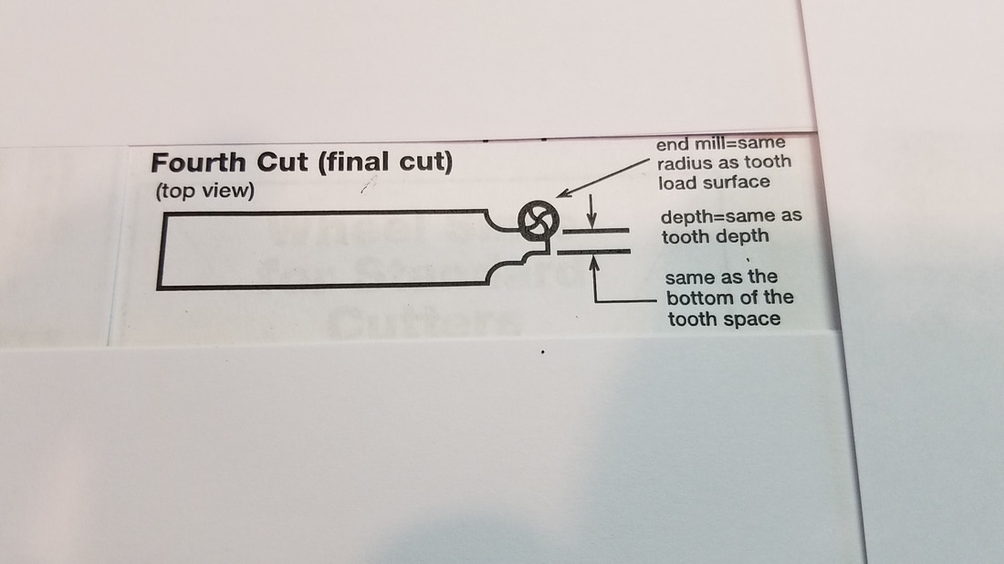
The 4th and final cuts are done very similarly. Again it is necessary to carefully re-zero the handwheels as done before only this time you will be zeroing against the cuts that were just made. The diameter of the end mill is determined by the radius of the tooth load surface. If you were cutting a clock wheel you could determine this radius by knowing the module and other pertinent dimensions and using Wild's book but as I mentioned earlier this gear has unusual tooth profiles and unusual spacing so I am just trying to duplicate the tooth profile. I held the ends of drill bits under a good tooth and used the drill size to determine the tooth radius. In this case I decided that using a 1/16th" end mill would be very close to giving the the correct tooth shape. (I find this difficult to do even with magnification so some trial and error may be necessary).
After re-zeroing the handwheels and putting in a 1/16" end mill it was time to calculate the last cuts. Referring to Jerry's handout again for the 4th cut I had to figure how much to take off of both the front and back of the cutter. The width of the final point of the cutter is to be the same as the space between the teeth of the gear. I used pin gauges to determine the space between each tooth and it was .035". The current cutter width after the 3rd cut was .095" so I had to take off .060" in the 4th cut divided over the front and the back so I had to take .030" off of each side. Since what was left was going to be the cutting surface I ran the mill at a high speed and took the remaining material in one pass on front and back. Also it was very important that the depth of the cut from the right hand side of the blank cutter moving toward the left is the height of the teeth which in my case was .065". After the last cut was made I measured the tip of the cutter in case I might have to take another thou or two off but my measurement was good so I was able to remove the cutter from the vice.
After re-zeroing the handwheels and putting in a 1/16" end mill it was time to calculate the last cuts. Referring to Jerry's handout again for the 4th cut I had to figure how much to take off of both the front and back of the cutter. The width of the final point of the cutter is to be the same as the space between the teeth of the gear. I used pin gauges to determine the space between each tooth and it was .035". The current cutter width after the 3rd cut was .095" so I had to take off .060" in the 4th cut divided over the front and the back so I had to take .030" off of each side. Since what was left was going to be the cutting surface I ran the mill at a high speed and took the remaining material in one pass on front and back. Also it was very important that the depth of the cut from the right hand side of the blank cutter moving toward the left is the height of the teeth which in my case was .065". After the last cut was made I measured the tip of the cutter in case I might have to take another thou or two off but my measurement was good so I was able to remove the cutter from the vice.
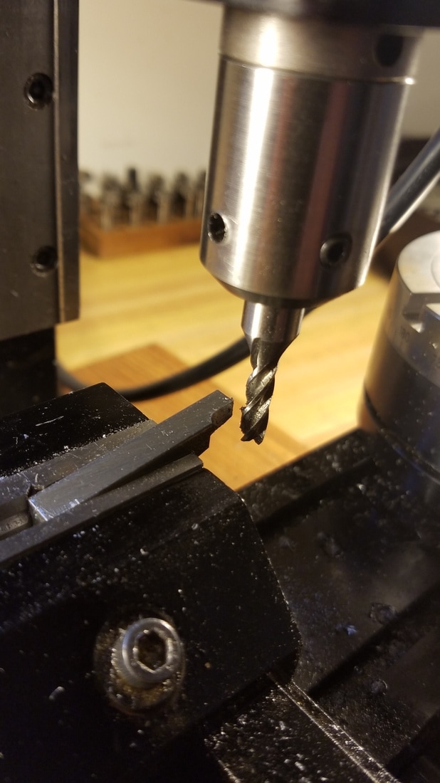
This is the cutter after the final cuts. |
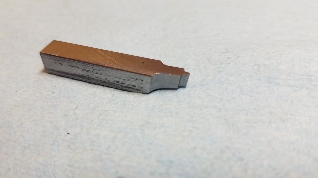
Another view of the single point cutter.
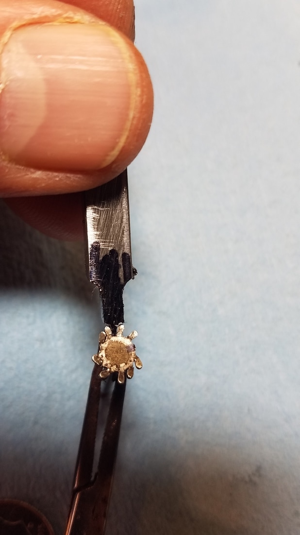
I painted the end of the cutter with a black magic marker for contrast. I am trying to find the best 2 teeth of the mangled gear to hold the cutter up to to see if I think the profile is correct. With this gear it is hard to say but it looks pretty good to me.
|
The only thing left to do with the single point cutter was to harden it. I heated it to bright red and quenched it. Then it needs to be tempered to a light straw color and quenched again. After the tempering then the top of the cutter needs to be sharpened by rubbing it on a sharpening stone. I did not have enough hands to take any pictures of the hardening or tempering process but there is lots of information on how to do it online. The best searches are probably for how to harden a chisel or a knife blade. I hope my description of the process has been helpful to anyone wanting to make a cutter for a gear or a clock wheel.
On page 2 will be how I used this cutter to make the new winding gear.
On page 2 will be how I used this cutter to make the new winding gear.
